")
")
")
The Control Center: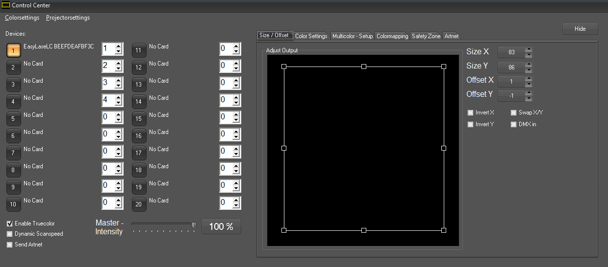
The timeline tracks assigned to the actual hardware output interfaces in the Control Center. Above picture shows the start page. One interface has been found in this example. Each hardware interface can be assigned a track index of 1-16.
There are some global settings, which apply to all hardware interfaces on the lower left side:
"Dynamic Scanspeed"
If the point number in the output buffer falls below a certain value the scan speed is automatically adjusted to a reasonable repetition rate.
"Send Artnet"
The DMX values per timeline track are also automatically sent via UDP/Artnet. The target address (universe, subnet) can be set in the tab "Artnet".
The output settings are on the right side of the window. These are multipliers to the world settings specified in RealTime. Set size and offset via dragging and dropping the shape. Fine adjustments can be made with the up/down arrows at the respective values.
The checkboxes "Invert x" and "Invert Y" invert the very axis. "Swap X/Y" swops the values, which allows for the use of 90° mounted laser systems.The checkbox "DMX in" activates the very interface as DMX receiver for external DMX signals.
Switch to the tab "Color Settings":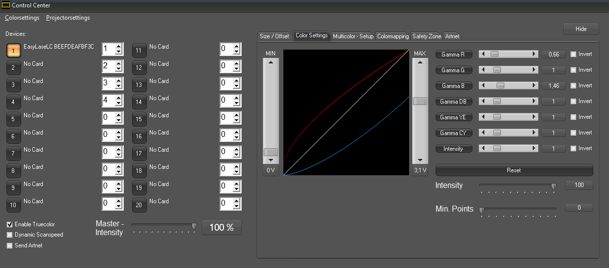
Set the color output parameters for the very interface here. The color to be adjusted can be selected with a click on the '"Gamma" + color' buttons.
The Min/Max faders at the side of the curves can be used to adjust offset and maximum values. The very Gamma slider influences on the form of the curve.
This it is possible to compensate overpower on a color channel or unlinear behavior of diode drivers.
See 2.2. White Balance for further details on how to use the Color correction option.
The fader "Intensity" specifies the maximum overall brightness for the very output hardware.
The fader "Min Points" reduces laser power if a certain amount of points is undercut.
Next is the tab "Multicolor Setup":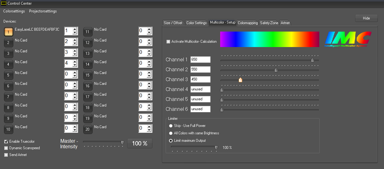
This feature is important for laser systems with more than three different output color channels. Usually these are OPSL equipped systems with additional color sources like yellow or cyan. If the Multicolor Setup is activated, the RGB values of a frame are recalculated to match the color lines, so all sources can perform as required.
At the bottom there is a general limiter function:
"Skip"
Function is disabled
"All Colors with same Brightness"
Single color values get reduced. Whit is 100% red + 100% + 100% blue. Thus white would be approx 3 times brighter than the single. On activating this function white would be 33% red, 33% green and 33% blue. Yellow would be 50% green and 50% red.
Tab "Colormapping":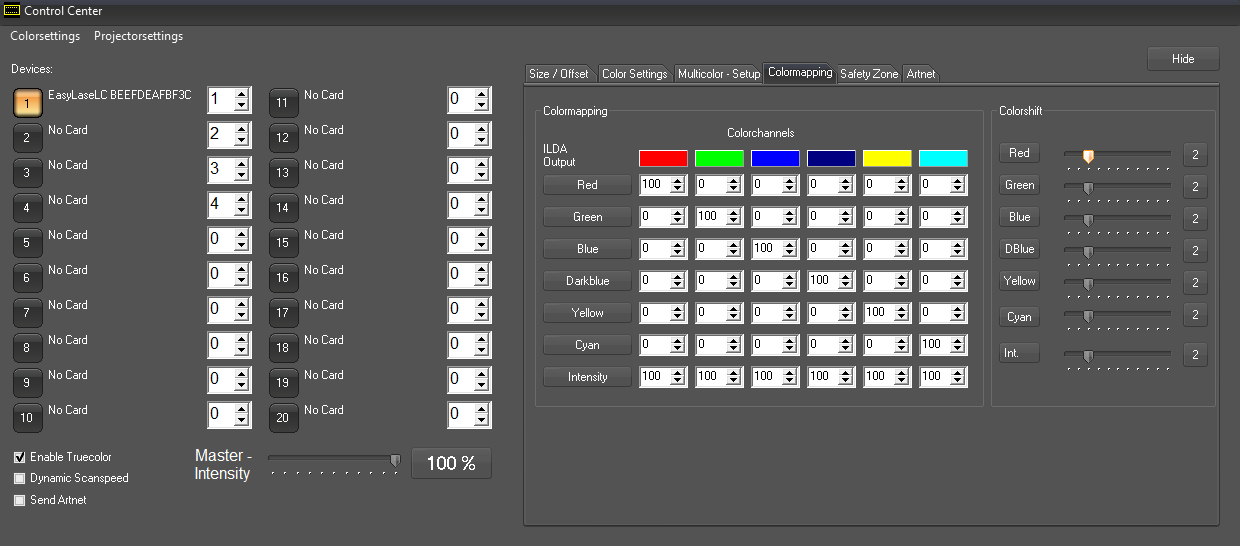
The tab "Colormapping" allows for routing certain colors to ILDA output color channels. The color shipft can be adjusted per color channel on the right side.
Tab "Safety Zone":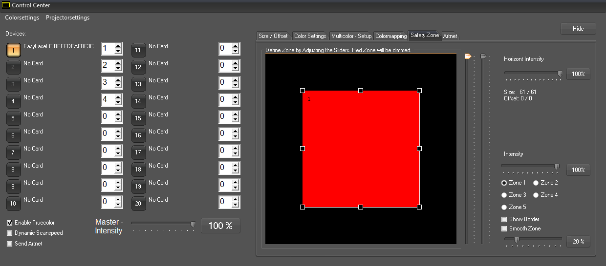
It is possible to create up to 5 safety zones via drag & drop. The laser power is reduced to the value assigned for "Intensity" in this area. This can be a hard cut or a smooth transition (Smooth Zone). A safety zone is only active if the intensity value is <100%.
A quick and easy - and in most cases sufficient, method of creating a safety zone is the horizont: A power reduction from top to bottom spanning the whole width of the projection area: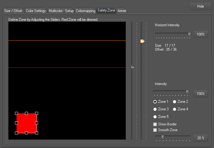
The orange and the red line can be adjusted with the faders next to the zone display. Laser output above the orange line is 100%. Below the red line, the intensity is as specified with Horizont Intensity fader. In the area between these lines the intensity fades. This creates a smooth dimming to the safety zone.
The 5 individually configurable safety zones can be configured that way: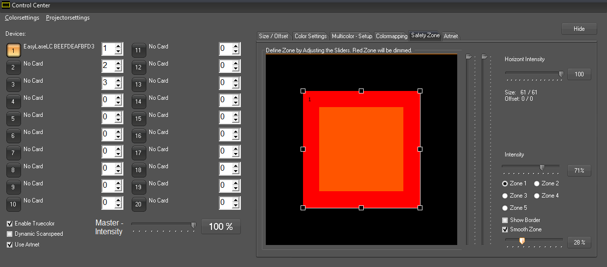
Click the checkbox of the zone to adjust (1-5). Use the controls to adjust size and position of the very zone. the intensity can be set with the "Intensity" fader. If Smooth Zone is activated, the safe zone gets a smooth framing, so there is no hard cut from full on to reduced intensity.
Of course it is only possible to reduce power if there are points to be reduced. Depending on picture size and interpolation parameters it is possible that a point is still in the 100% intensity area and the next point is already in the orange area. In this case there of course is no fading visible. Due to these circumstances it makes sense to specify the safety zone slightly bigger than necessary.
The setting of safetyzones becomes easier if a grid pattern is projected.
Tab "Artnet":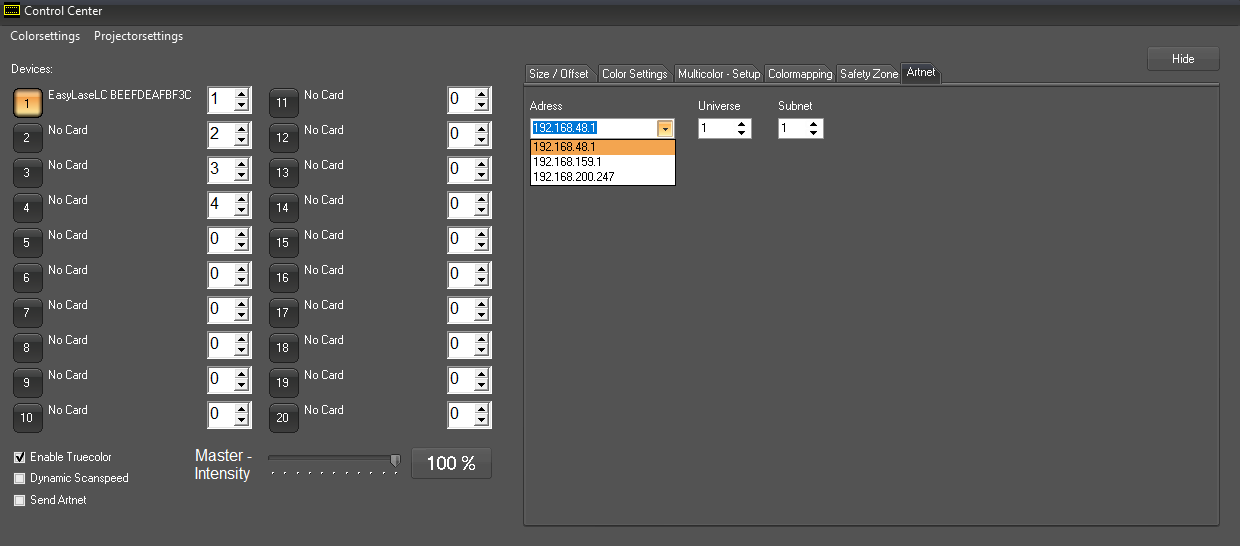
If the option "Send Artnet" is activated it is possible to specify the IP Address, the universe and the subnet to which the DMX-Out values of this track shall be sent.